Please read the user manual before installing, operating, maintaining, or inspecting this product.
Be sure to read the safety information and precautions in this manual and operate the product accordingly.
1.2 Usage Precautions
Check that there are no abnormalities in the product's appearance. Abnormalities may pose risks of electric shock or fire.
Do not touch external terminals carelessly. When power is applied to the main power terminals, electricity is supplied to internal components and circuits. Contact with the body may cause death or serious injury.
Always close the front cover when operating this product. Foreign objects or body contact are extremely dangerous. When opening the front cover, stop operation and wait until power is disconnected.
When inspecting, repairing, or maintaining this product, be sure to disconnect all related power sources and perform repairs or maintenance only after power is turned OFF.
Connect the ground wire (F.G.) when installing the product. Leakage current may flow through the product. This prevents personal injury from high voltage.
Remove foreign objects or heat-generating items from around or on this product. If smoke or unusual odors occur, stop operation and disconnect power. Continued use may cause malfunction, electric shock, or fire.
Do not modify, repair, alter, or damage this product without authorization.
When repairing, inspecting, or replacing parts, contact an authorized service representative or the company service center.
1.3 Installation Precautions
Install this product outdoors in a location free from moisture and dust, away from direct sunlight and high-temperature heat sources.
Wiping this product with a wet cloth may cause electric shock and injury.
Never use flammable substances or spray materials on this product. Such substances may cause explosion or fire.
Avoid placing other electrical appliances near this product. Malfunctions or noise may occur in those appliances.
Wiring and inspection of this product must be performed by qualified technicians.
2. Overview
2.1 Features
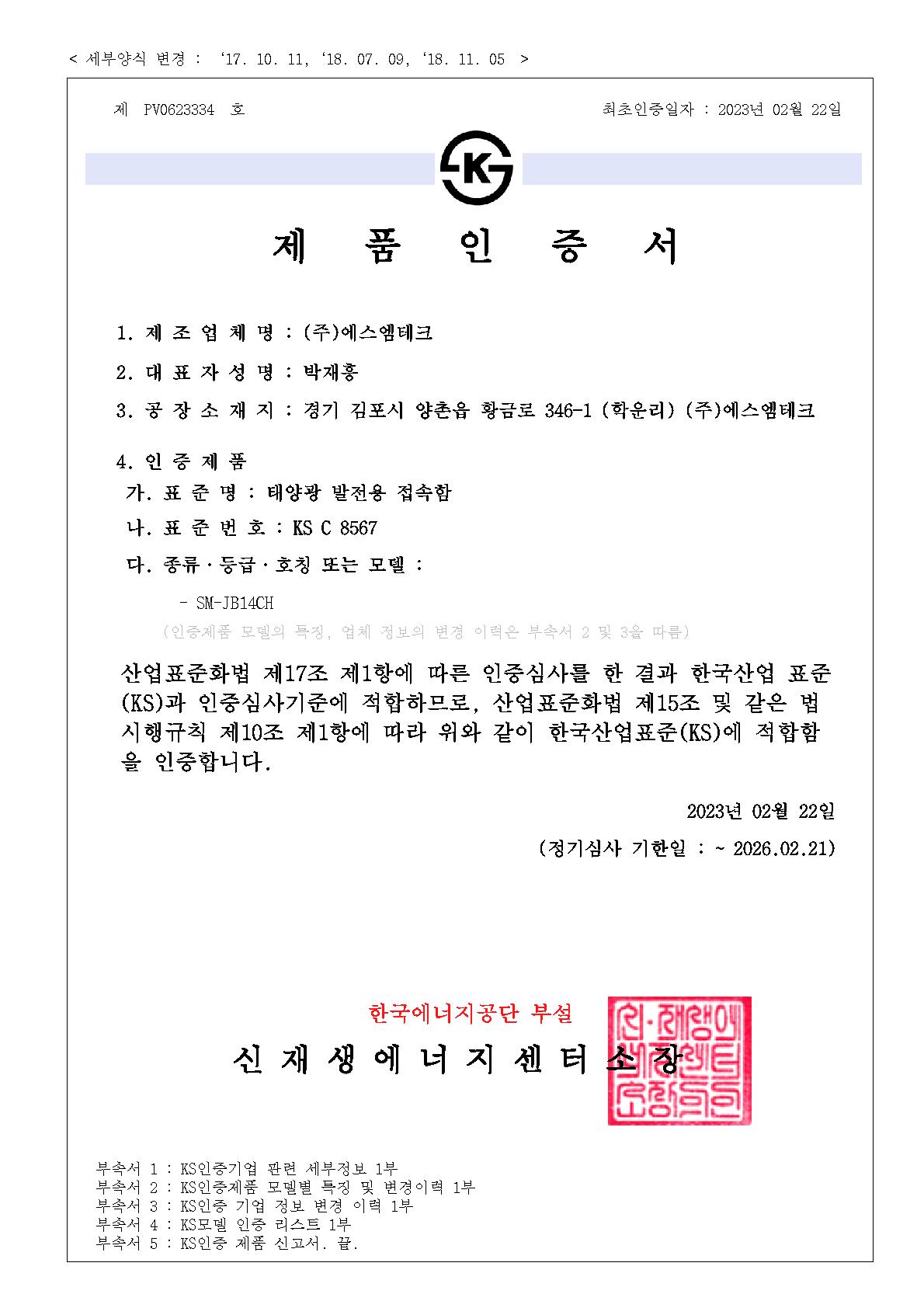
Manufactured in accordance with KS C-8567 standard
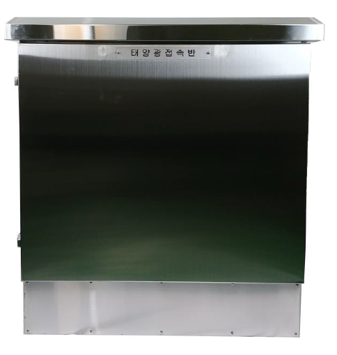
Made of SUS (Stainless Steel Used) material for outdoor environments
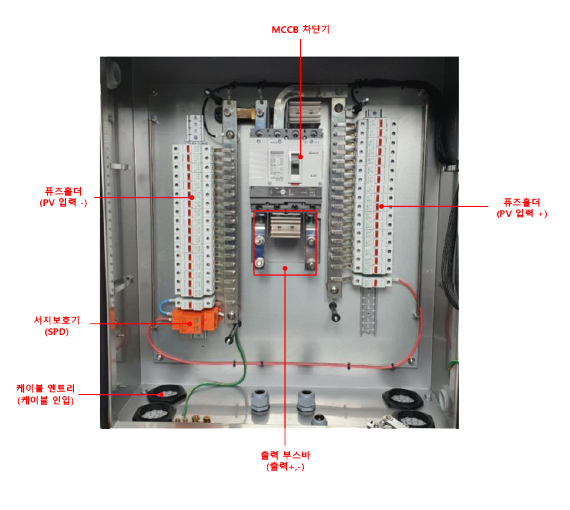
Entire PV DC input/output sections designed with busbar wiring to minimize fire risk
String-level fuses protect against overcurrent
Surge protector (SPD) installed to protect the system from induced surges
PV application main circuit breaker (MCCB) safely disconnects all connected string current
2.2 Internal Configuration
2.3 Product Specifications
Category
Description
Enclosure
Dimensions
700(W) x 950(H) x 280(D) mm
Weight
Approx. 50 kg
Material
SUS304
Installation Method
Freestanding, fixed with anchor bolts
Electrical / Environmental Specifications
Rated Voltage (STC)
DC 833V
Maximum Open-Circuit Voltage
DC 1000V
Rated Current (per string)
DC 14.2A
Rated Output Current
DC 198.8A
DC Circuit Breaker (MCCB)
Rated voltage (Ue): 1000VDC / Rated current (In): 250A / Rated breaking current (Icu): 20kA
Surge Protector (SPD)
Maximum continuous operating voltage (Uc): 1000VDC / Nominal discharge current (In): 20kA
Fuse
Rated voltage (Ue): 1000VDC / Rated current (In): 25A / Rated breaking current (Icu): 20kA